This is how the world’s mightiest offshore cranes work
The giant cranes onboard crane vessels may all look similar, but crane specialists know better. Heerema Marine Contractors had important choices to make for the 10,000-tonne cranes of the Sleipnir. Both for the crane type and its major sub-systems.
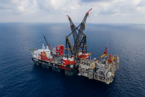
With a maximum lift capacity of 20,000 tonnes, Sleipnir is the strongest heavy-lift vessel in the world and in its first year of operation the mighty ship immediately set a new record, lifting a 15,300-tonne topside in Israel for Noble Energy’s Leviathan development.
To handle the incredible loads, Heerema chose to install tub cranes which have been designed by Huisman Equipment. A dedicated design platform was developed to implement Heerema’s own ideas on the crane design and systems. This also involved redundancy requirements, which were new to crane designs.
Heerema has extensive experience operating tub cranes as this type of crane was also installed on other Heerema vessels like the Balder (1x 4,000 tonnes and 1 x 3,000 tonnes) starboard, the Thialf (2 x 7,1000 tonnes) and the Aegir (1 x 4,000 tonnes). But the cranes of the Sleipnir topple them all, as can be seen in the cranes’ main dimensions below.
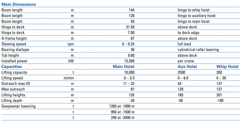
Main hoist capacities
The Sleipnir’s main cranes were designed for lifting a static weight of 10,000 tonnes at a radius of 27 to 48 metres. The crane design takes an additional factor of 1.1 into account to allow for dynamic conditions, along with 3 degrees side-lead and 1 degree off-lead. These values allow for vessel static and dynamic angles and limited load swings in lateral and longitudinal directions.
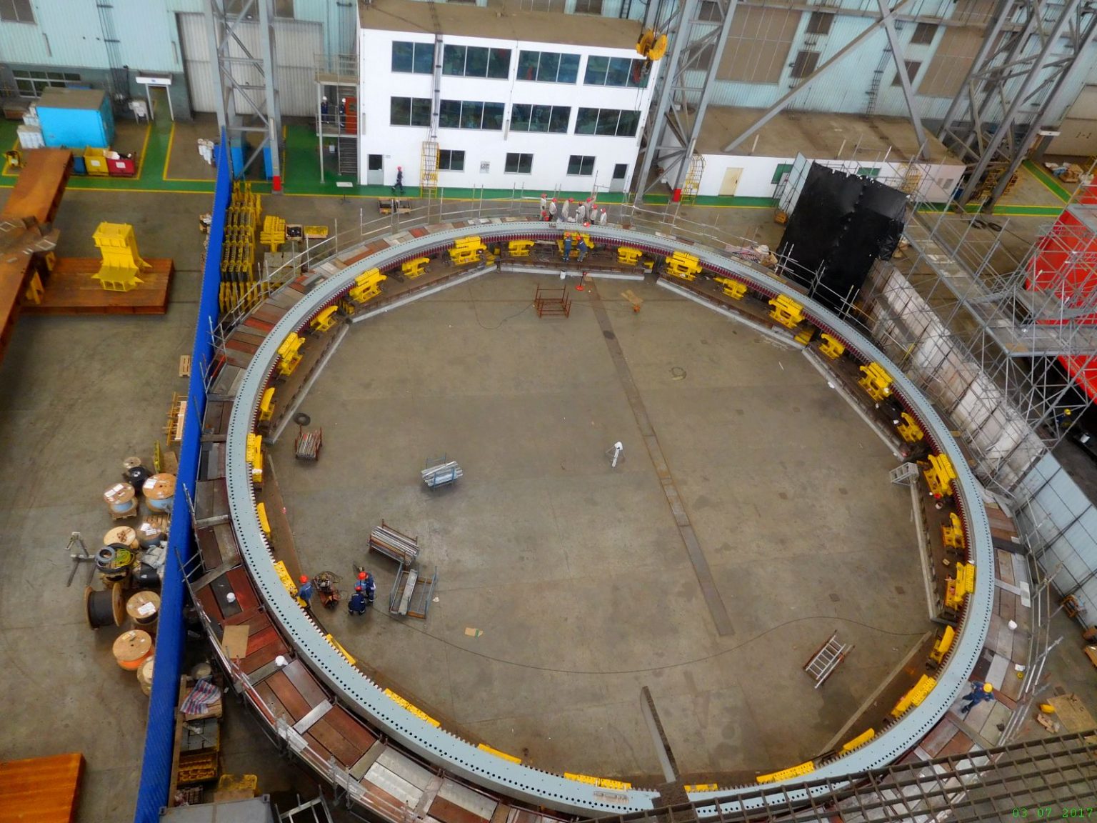
The vessel’s stability, strength and ballast capacity were optimised in order to utilise the maximum lifting capacity of the two cranes. The cranes are mounted on circular crane tubs, structurally integrated with the vessel’s deck box at the forward end. A large slewing bearing assembly of 30-metre diameter is fitted on top.
The cranes do not only excel in lifting capacities, but also in the available room below the main tackles. See the figure below, where the Sleipnir crane curve is shown, with the curve of the Thialf plotted for comparison.
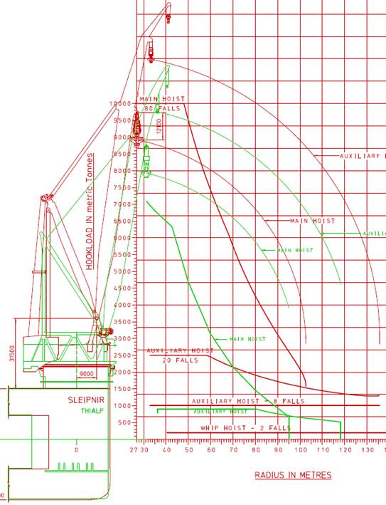
The crane curves of the Sleipnir and Thialf compared.
The crane curves are based on the capacity of the hoisting and booming tackle and the crane load moments. They start in boomed-up condition, down to the lowest feasible range. The smaller figures next to the crane curves show the feasible sections of a module at increasing outreach for both crane systems.
When steeply boomed up, the Sleipnir cranes can handle objects with very large cross sections, as shown by the blue blocks. When boomed out to limit with maximum load, very large cross sections are feasible for the Sleipnir cranes, as shown by the yellow and red blocks. This pattern persists till the very end of the crane’s outreaches as shown by the green and purple blocks.
Capacities auxiliary and whip hoist
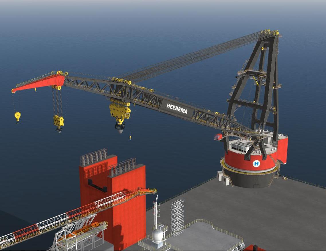
Spectacular are the attainable heights and outreaches of the auxiliary hoist and whip hoist. This was accomplished by the long and slightly angled boom extension for the auxiliary hoist and the further angled boom tip for the whip hoist.
A load of 2500 tonnes can be boomed up to a height of 185 metres above water level at transit draft. A load of 1400 tonnes can be handled through the entire boom range down to horizontal. The same can be accomplished with the whip hoist of 200 tonnes, which can reach a height of 201 metres at vessel transit draft and can extend 137 metres from the bow. The whip hoist is certified for 15 tonnes man riding.
A load of 2500 tonnes can be boomed up to a height of 185 metres above water level.
In this respect, it should be noted that in the operational life of a crane vessel, a maximum lift may occur once or twice a year, while auxiliary and whip hoists are being used on a daily basis.
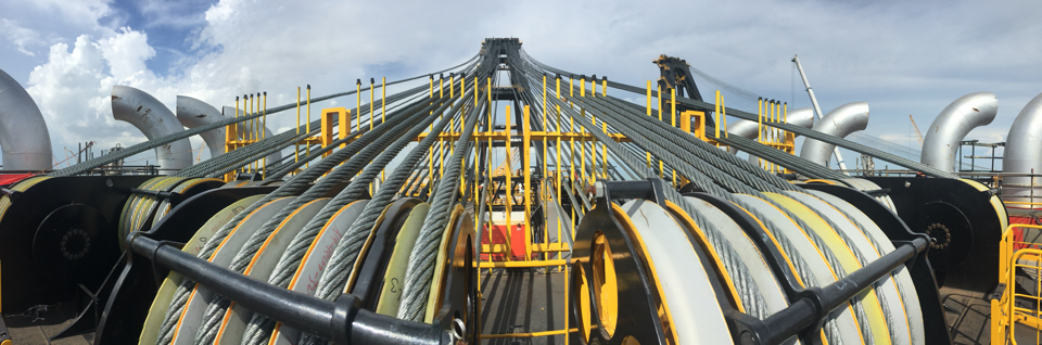
Winches and wires
The crane winches, both for hoisting and booming up, are based on identical concepts. Each winch consists of the following elements: a lebus wire rope drum, up to nine layers of 72 mm wire, minimum breaking load 474 tonnes, a planetary gearbox, six electro motors of 300 kW each, AC driven, 0 – 3000 rpm, and a disc spring parking brake.
The high-speed hoisting winches of the main hoist tackle can be electrically controlled for heave compensation. This will improve offshore workability.
Because of the long distance between sheaves and winches, a spooling arrangement was not necessary. Line pulls act on the winch drums directly, avoiding a conventional traction winch and spooling arrangement.
At the request of HMC, Huisman designed a boom hoisting tackle and a main hoist lifting wire arrangement based on single failure redundancy. This is a novelty in offshore crane designs.
Huisman designed a boom hoisting tackle and a main hoist lifting wire arrangement based on single failure redundancy.
The crane boom is equipped with four tugger winches of 50 tonnes each to stabilise the load during hoisting and lowering. These winches are actively controlled for dampening possible load swings. Their position, speeds and dampening effects were assessed by HMC vessel and lift simulations. Additionally, three 20-tonne tugger winches were fitted for sling handling or small objects when preparing an offshore lift.
For lifting operations, wires have to be reeved in and out frequently, to adjust for appropriate lifting force and lifting depth. Without special arrangements, reeving would require on the spot replacement of wire end sockets and renewing of splices. In order to reduce vessel waiting times, Huisman developed a Quick connector of compact design, enabling quick reeving and passing of the connector through sheaves grooves without clashes.
Counter ballast and separable main block
Offshore cranes are often designed with counter ballast weights. Ballast fitted aft of the rotation centre can effectively compensate the weight of the crane boom and light lifts. It avoids the need for operating the vessel ballast system and manning-up of pump rooms.
However, ballast weights do permanently reduce a vessel’s stability and hence the outreach of a crane. Furthermore, it adds weight at the wrong end of the vessel, increasing the water ballast requirement and its draft.
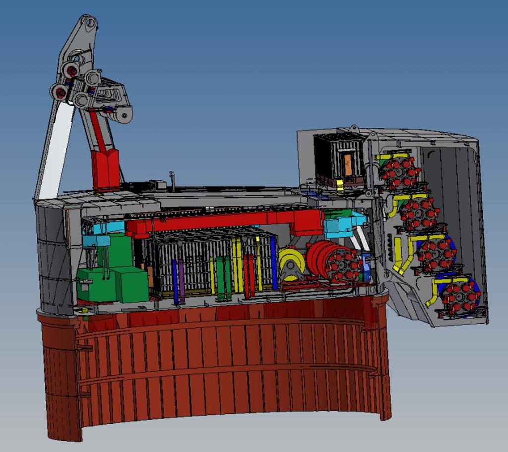
The Sleipnir cranes have no such ballast weights. Instead, the cranes are equipped with a “back-pack” type winch room, containing the four main hoist and the four boom hoist winches. Their weight and the significant weight of their wire ropes counteracts the boom weight in light lifting modes in all slewing positions.
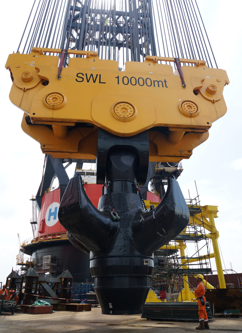
A further step to this effect is the design of the main block (shown in the picture above). Parts of it can be stowed in the boomrest when not in use. This will reduce the boom weight during the many light lifting operations and hence save energy. It also enhances the free sight from the operator’s cabin. HMC spent a lot of effort implementing crane operators’ experience in the location and design of the operator’s cabin.
Slewing bearing arrangement
A large bearing ring structure enables unrestricted rotation of the crane. It transfers the crane loads to the ship. The inner bearing ring is fixed to the circular ship-based tub structure. Teeth racks are fitted to the inner circle enabling crane slewing, as driven by twelve vertical gearwheels.
The inner bearing ring is enclosed by an integrated outer and upper ring structure. It holds it like a claw. Roller bearing units are fitted in slots up and below the inner teeth ring. The units contain cylindrical rollers fitted in cages. The rollers are made of hardened bearing steel alloy, designed and tested to high point loads. The rollers are running on hardened raceway plates.
For transferring horizontal forces, the bearing is fitted with inner sliding surfaces. The bearing arrangement replaces the king-pin structures applied in conventional crane designs and reduces the crane weight significantly. The closed bearing assembly will also save maintenance and grease.
Design of crane house and hoisting frame
A separate boom hinge support structure was designed for taking the loads of the forward legs of the hoisting frame. The crane house was strengthened to transfer and evenly spread the loads to the roller bearing. All the legs of the hinge and hoisting frame are mounted on the upper part of the crane house. The crane house is mounted on the roller bearing assembly transferring the forces to the vessel’s crane tub.
The roller bearing dictates strict deformation restrictions. Therefore, the entire crane house structure with integrated crane legs and bearing assembly has been analysed on strength and deflection. Its structural stiffness has been tuned to the allowable deformations of the roller bearing assembly. As a result of this integrated design approach, a weight saving of 600 tonnes per crane could be achieved, leading to a crane weight of 8900 tonnes. This has resulted in an extra 4.0-metre outreach at maximum capacity.
Its structural stiffness has been tuned to the allowable deformations of the roller bearing assembly
Engineering challenges
Large scale effects invariably require special engineering. This concerned, for instance, the many chord-brace connections of the crane boom. Chords and braces were made of plate material STE 690. The welds on the tub flange have a thickness of 300 mm.
Meeting the Charpy criteria for these welds was very difficult. Dedicated laboratory tests had to be conducted to verify its brittleness. As a major offshore structure, a comprehensive fatigue analysis of the crane structure has been carried out, based on HMC’s user lift spectrum.
The fabrication method of the cylindrical roller elements of the main bearing had to be adjusted. Holding it by pins in the centre boring for machining, appeared to cause fractures during pressure testing. Therefore, another manufacturing method had to be found.
A number of castings had to be rejected, because cracks were found after weeks of carefully cooling down
Due to the large size of the 10,000-tonne crane hook, its design and load patterns were a true challenge. The design was created in close cooperation with HMC contributing its expertise into the design of the prongs and basic concept of the total hook assembly. Then, manufacturing challenges had to be dealt with. A number of castings had to be rejected because cracks were found after weeks of carefully cooling down, in spite of the very experienced manufacturer.
Power system
Electrical power as generated by the vessel is transferred to the crane systems by two independent engine rooms via slip rings, located in the tub/crane house centre. Slip rings enable the transfer of continuous electrical power during 360 degrees of rotation.
The slip ring assembly was designed with two bodies: a lower section, delivering 11 kilovolts main power, and an upper section, delivering 440 Volts (supply and emergency) power to the crane systems. On top thereof, there is a compartment with signal and fibre optical transfer.
The entire electrical system of the crane was designed with a consistent redundancy philosophy. The system consists of two 11 kV/640 V transformers and two switchboards, feeding four Erooms. The motors of all winches and slewing drives are connected to these four E-rooms, ensuring power after a single failure of any subsystem or electrical component. Therefore, when such a failure occurs, the crane can continue operating at full load, although at half power and speed. This guarantees a safe termination of a lift, as confirmed by special failure mode and criticality analyses.
The single failure design approach was implemented throughout the crane subsystems. This includes the cooling system of the electrical and mechanical component. Some are water-cooled, such as the transformers and inverters. Others are air-cooled, like the E-rooms, gearboxes and e-motors.
The single failure design approach was implemented throughout the crane subsystems.
In principle, the air cooling system consists of condensers, chillers and air handlers with outflow channels directed at these components. In view of the very large powers involved, an internal cooling system is essential to avoid large external air flows that would bring undesirable noise and dust.
The search for super capacity
The industry’s demand for installing larger integrated structures in a single lift is driving the concept of super semi-submersible crane vessels. Or is it the super capacity that drives the industry? In any case, the Sleipnir sets the pace to a very high level and the industry has responded.
This article was originally published in the December 2018 issue of our sister publication SWZ|Maritime, providing daily technology fixes for marine and naval engineers. This analysis is written by Ir Rob Bos, who was specialised in the design of offshore vessels and FPSO installations.